Concepts and terms of MASS
Nodes
A node is a general term that refers to multiple, more specific objects.
Nodes include:
- Controllers
- Machines
- Devices
node’s life cycle:
Controllers
Machines
A machine is a node that can be deployed by MAAS.
Devices
A device is a non-deployable node.
Static or dynamic IP addresses and DNS names can be assigned to any device or parent node.
Pods
Pods, also called composable hardware, allow for the dynamic composition of machines from a pool of available hardware resources (e.g. disk space, memory, cores).
Zones
A physical zone, or just zone, is an organisational unit that contains nodes where each node is in one, and only one, zone.
Regions
A region is an organisational unit one level above a zone.
Series
A series is essentially an operating system version.
Images
An image is used to provision a machine. As soon as you install MAAS, images are imported based on what series you have selected. MAAS won’t work until it has imported the necessary images.
Fabrics
A fabric connects VLANs.
Consequently, it would be impossible for two VLANs to communicate with each other. A fabric makes these VLAN-to-VLAN connections possible.
You could describe a fabric as a VLAN namespace. It’s a switch or a combination of switches that use trunking to provide access to specific VLANs.
The following conceptual diagram shows two fabrics in the same data centre or region, each using distinct VLAN ranges and their associated subnets:
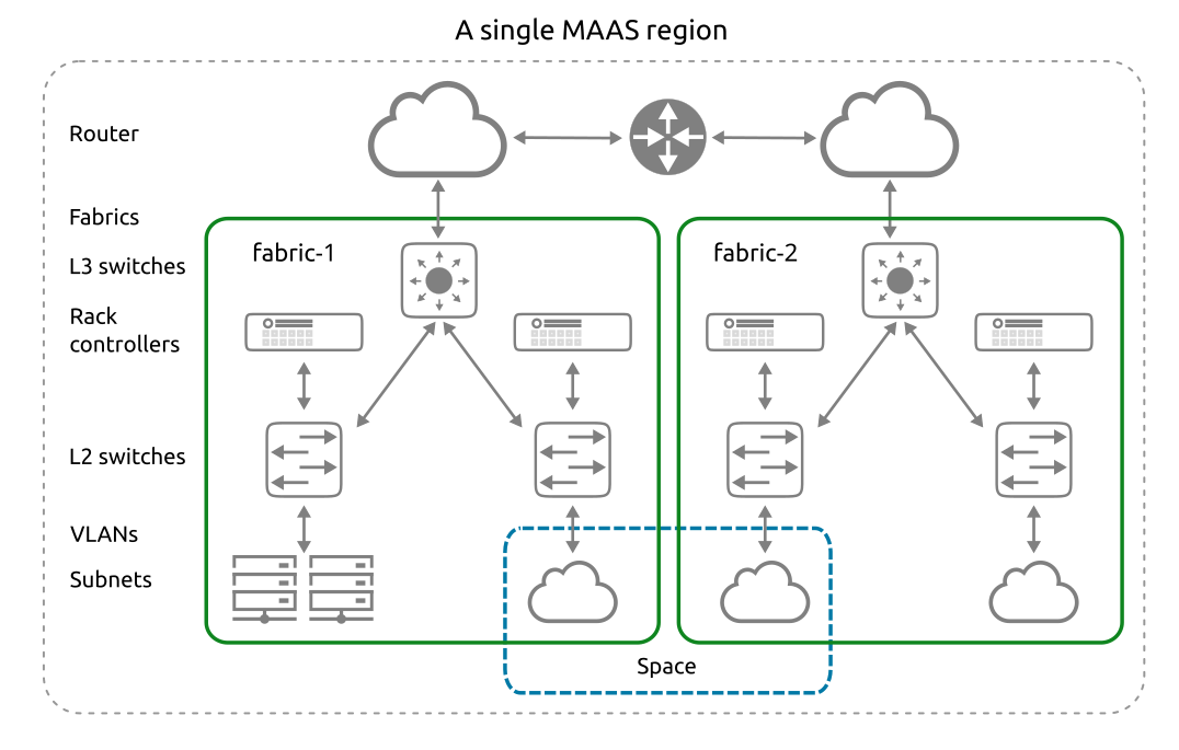
Spaces
A space is a logical grouping of subnets that can communicate with one another.
Spaces can be arranged to group subnets according to various parameters.
One of the most common examples is a DMZ space, which might group subnets presenting a web interface to the public Internet. Behind this DMZ would be specific applications that aren’t allowed to interact directly with the user, but instead must interact with a Web UI in the DMZ space.
Tags
A tag (not to be confused with VLAN tags) is user-created and associated with nodes based on their physical properties.
Subnets
A subnet is a “layer 3” network, defined by a network address and a network mask length (in bits) and usually written in “CIDR” format. MAAS supports IPv4 and IPv6 subnets. Examples include:
10.0.0.0/8
172.16.0.0/12
192.168.0.0/16
2001:db8:4d41:4153::/64
VLANs
VLANs (Virtual LANs) are a common way to create logically separate networks using the same physical infrastructure.
DHCP relay
A DHCP relay, or relay agent, is a network device that forwards requests and replies between a DHCP client and a DHCP server when both are not on the same physical subnet.
Interfaces
Physical
After a node is commissioned, MAAS discovers its physical interfaces.
MAAS always creates a device with at least one physical interface.
Before deployment, a MAAS administrator can configure additional interfaces on the node, including one or more of the types mentioned below.
Bond
A bond interface is capable of aggregating two or more physical interfaces into a single logical interface.
VLAN
A VLAN interface can be used to connect to a tagged VLAN, if the node is connected to an authorised port.
Machine actions
Machine actions are essentially “things you can do with nodes”.
You can trigger them via the web UI or the MAAS CLI.
Abort
You can abort any action that permits retries. Currently, only commissioning and deployment permit retries.
Acquire
Allocates (reserves) a node to the MAAS user performing the action (and currently logged in).
Changes a node’s status from ‘Ready’ to ‘Allocated’.
Commission
This action commissions a node, changing a node’s status from ‘New’ to ‘Commissioning’ to ‘Ready’.
Commissioning enables MAAS to build a detailed inventory of RAM, CPU, storage, NICs and accelerators like GPUs.
Delete
This action removes a node from MAAS
Deploy
This action, which includes ‘Power on,’ deploys a node, changing a node’s status from ‘Ready’ (or ‘Allocated’) to a deployed status.
Exit rescue mode
This action changes a node’s status from ‘Rescue mode’ to the ‘Exiting rescue mode’ transitory status and then back to its original status when the operation is complete.
Node statuses
Allocated
The node is allocated (reserved) to a MAAS user. See node action ‘Acquire’.
Broken
The node is broken. See node action ‘Mark broken’.
Commissioning
The node is in the process of commissioning. See node action ‘Commission’.
Deployed
The node is deployed. See node action ‘Deploy’.
The visible status will be the name of the chosen OS (e.g. ‘Ubuntu 16.04 LTS’).
Deploying
The node is in the process of deploying. See node action ‘Deploy’.
The visible status will be Deploying to ‘OS’, where ‘OS’ is the name of the OS being deployed (e.g. ‘Deploying to Ubuntu 16.04 LTS’).
Entering rescue mode
The node is in the process of entering rescue mode. See node action ‘Rescue mode’.
Exiting rescue mode
The node is in the process of exiting rescue mode. See node action ‘Exit rescue mode’.
Failed Commissioning
The node failed to commission.
Failed Deployment
The node failed to deploy.
Locked
It’s not strictly a status, but a machine showing a ‘padlock’ symbol adjacent to its name is in a locked state.
New
This status represents the first stage of a node’s life in MAAS. Typically, a node with this status has just been added to MAAS.
Ready
A node bearing this status has been commissioned and is ready for use, including the necessary BMC credentials. MAAS can start or stop this machine, and allocate or (re)deploy it with a fresh operating system.
Rescue mode
The node is in rescue mode and is ready to accept SSH connections. See node action ‘Rescue mode’.
Package repositories
Package repositories managed within MAAS can be of two types:
- Ubuntu package repositories
- Personal Package Archives (PPA)
Personal Package Archives (PPA)
A Personal Package Archive (PPA) is a Launchpad-based method for any individual (or team) to build and distribute packages for Ubuntu.
Brief network tutorial
The following is a brief network tutorial, provided as a tool to synchronize understanding.
DHCP
The Dynamic Host Control Protocol is a network management system in which a server (or group of servers) dynamically assigns IP addresses and other network parameters to a network device.
DHCP operates using the “DORA” model: Discovery, Offer, Request, and Acknowledge:
- Potential DHCP clients broadcast a DHCPDISCOVER message on its attached subnet using destination address 255.255.255.255.
- connected DHCP server receives the DHCPDISCOVER message and sends a DHCPOFFER message, containing an IP address that the client may use.
- The client replies with a DHCPREQUEST message, requesting the offered address.
- The DHCP server responds with a DHCPACK (acknowledgement) which includes various important configuration parameters, such as the lease duration.
(Of course, there is much more to DHCP, but what’s covered here should be sufficient understanding for using MAAS.)
Client
In the client/server age, the lines between client and server are blurred and sometimes reversible.
For the purposes of MAAS and general networking principles, we can define a “client” as a node that uses shared resources via a network. If that same client provides shared resources to other nodes, it could also be considered a server.
Server
A server is a node that provides shared resources to clients via a network.
If that same server uses shared resources from other nodes, it could also be considered a client, but only in that context.
Network interface
A network interface, often referred to as a “network interface card” or NIC, is either a separate physical card connected to a node, a set of circuits embedded on a node’s motherboard, or a radio transceiver attached to a node in some way.
All network connections require a NIC. The terms “port” and “adapter” are also used to refer to a network interface.
MAC address
A MAC or “media access control” address is a unique address or “physical address” associated with a network interface.
Every computer in the world theoretically has a unique MAC address. You can identify a node’s IP address with the command ipconfig /all.
Network cable
Network cables are special cables that connect non-wireless-based nodes.
Packet
A packet is a unit of network traffic. It may or may not represent a complete message.
Repeater
Technically, a repeater is a network signal amplifier with two RJ45 connectors which adds one maximum length (for the cable type) to the network connection or “run.”
Hub
Hubs essentially started as repeaters. While they may be able to connect more than two computers together
Switch
A switch is a “smart” device that connects cables from nodes to make networks.
Network topology
Topology describes how nodes are connected to a network, specifically referring to the shapes made by the cables and the paths that packets can take.
Patch panel
A patch panel is simply a 24- to 48-port panel of connectors that can link together three- to ten-foot cables
LAN
Besides topology, networks can also be classified by their size, range, or “reach.” One such classification is the Local Area Network (LAN), which connects computers in close proximity (about 300 feet).
WAN
A WAN (wide area network) is a network which connects LANs across large geographic distances, e.g., thousands of miles.
MAN
A metro area network or MAN connects LANs over a smaller area, like a city or urban footprint. Basically, if it isn’t really a WAN, but you can’t connect it with cables, it’s usually considered a MAN.